- 您现在的位置:买卖IC网 > Sheet目录496 > OPB705W (TT Electronics/Optek Technology)SNSR OPTO TRANS 3.81MM REFL C-MT
Reflective Object Sensor
OPB703 through OPB705, OPB703WZ through OPB705WZ,
OPB70AWZ through OPB70HWZ
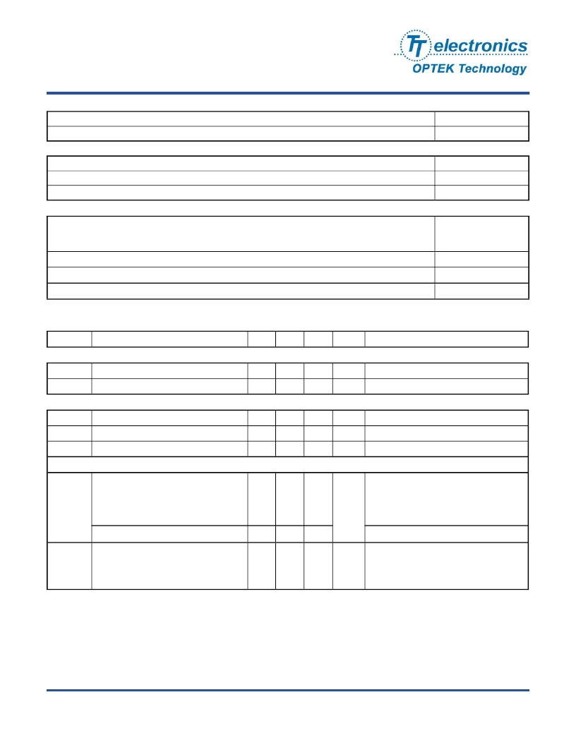
Absolute Maximum Ratings (T A =25°C unless otherwise noted)
Storage Temperature Range
Lead Soldering Temperature [1/16 inch (1.6 mm) from the case for 5 sec. with soldering iron]
Input Diode
Forward DC Current
Reverse DC Voltage
Power Dissipation
Output Photodetector
Collector-Emitter Voltage
Phototransistor
Photodarlington
Emitter-Collector Voltage
Collector DC Current
Power Dissipation
Electrical Characteristics (T A = 25 ° C unless otherwise noted)
(OPB703, OPB703WZ, OPB704, OPB704WZ, OPB705, OPB705WZ, OPB704G, OPB704GWZ, OPB70HWZ)
-40°C to +80° C
240° C (1)
40 mA
2V
100 mW (2)
30 V
15 V
5V
25 mA
100 mW (2)
SYMBOL
PARAMETER
MIN
TYP
MAX
UNITS
TEST CONDITIONS
Input Diode (See OP265 for additional information — for reference only)
V F
I R
Forward Voltage
Reverse Current
-
-
-
-
1.7
100
V
μA
I F = 40mA
V R = 2 V
Output Phototransistor (See OP505 for additional information — for reference only)
V (BR)CEO
V (BR)ECO
I CEO
Collector-Emitter Breakdown Voltage
Emitter-Collector Breakdown Voltage
Collector Dark Current
30
5
-
-
-
-
-
-
250
V
V
nA
I CE = 100 μA
I EC = 100μA
V CE = 10 V, I F = 0, E E =0
Coupled
On-State Collector Current
OPB70HWZ
0.60
-
3.5
I C(ON)
OPB703, OPB703WZ
OPB704, OPB704WZ
OPB705, OPB705WZ
OPB704G, OPB704GWZ
0.30
0.20
0.15
0.50
-
-
-
-
2.5
2.5
1.0
6.0
mA
V CE = 5 V, I F = 40mA , d = 0.15” (3)(7)
V CE = 5 V, I F = 40mA , d = 0.20” (3)(6)
Crosstalk
I CX
OPB703, OPB703WZ
OPB704, OPB704WZ, OPB70HWZ
OPB705, OPB705WZ
-
-
-
-
-
-
20
20
10
μA
V CE = 5 V, I F = 40mA (6)
Notes:
(1) RMA flux is recommended. Duration can be extended to 10 seconds maximum when flow soldering.
(2) For OPB703, OPB704 and OPB705, derate linearly 1.67 mW/° C above 25° C.
(3) For OPB703WZ, OPB704WZ, OPB705WZ, OPB70BWZ, OPB704G, OPB704GWZ and OPB70HWZ derate linearly 1.82 mW/° C
above 25° C.
(4) The distance from the assembly face to the reflective surface is d.
(5) Crosstalk (I CX ) is the collector current measured with the indicated current in the input diode and with no reflecting surface.
(6) Measured using Eastman Kodak neutral white test card with 90% diffuse reflectance as a reflecting surface. Reference: Eastman
Kodak, Catalog # E 152 7795.
OPTEK reserves the right to make changes at any time in order to improve design and to supply the best product possible.
Issue D 03/2012
Page 4 of 9
OPTEK Technology Inc. — 1645 Wallace Drive, Carrollton, Texas 75006
Phone: (972) 323-2200 or (800) 341-4747 FAX: (972) 323-2396 sensors@optekinc.com www.optekinc.com
发布紧急采购,3分钟左右您将得到回复。
相关PDF资料
OPB707B
SENSR OPTO TRANS 1.27MM REFL PCB
OPB716Z
SENSR OPTO REFL 12.7MM PANEL MNT
OPB730F
SNSR OPTO TRANS 6.35MM REFL TO72
OPB732W
SNSR OPTO TRANS 76.2MM REFL C-MT
OPB745W
SNSR OPTO TRANS 3.81MM REFL C-MT
OPB755T
SENSR OPTO TRANS 5.59MM REFL PCB
OPB773T
SENS OPTO REFL 2.03MM-5.58MM PCB
OPB780Z
SENSOR REFLECTIVE OBJECT
相关代理商/技术参数
OPB705WZ
功能描述:光学开关(反射型,光电晶体管输出) Reflective Sensor RoHS:否 制造商:Fairchild Semiconductor 感应距离:1 mm 输出设备:Phototransistor 集电极—发射极最大电压 VCEO:30 V 最大集电极电流:20 mA 正向电压:1.2 V 反向电压:5 V 最大工作温度:+ 85 C 最小工作温度:- 25 C 安装风格:SMD/SMT 封装:Reel
OPB706A
功能描述:光学开关(反射型,光电晶体管输出) Output Phototranstr Input Diode RoHS:否 制造商:Fairchild Semiconductor 感应距离:1 mm 输出设备:Phototransistor 集电极—发射极最大电压 VCEO:30 V 最大集电极电流:20 mA 正向电压:1.2 V 反向电压:5 V 最大工作温度:+ 85 C 最小工作温度:- 25 C 安装风格:SMD/SMT 封装:Reel
OPB706B
功能描述:光学开关(反射型,光电晶体管输出) Reflective Sensor RoHS:否 制造商:Fairchild Semiconductor 感应距离:1 mm 输出设备:Phototransistor 集电极—发射极最大电压 VCEO:30 V 最大集电极电流:20 mA 正向电压:1.2 V 反向电压:5 V 最大工作温度:+ 85 C 最小工作温度:- 25 C 安装风格:SMD/SMT 封装:Reel
OPB706B
制造商:TT Electronics / OPTEK Technology 功能描述:ASSEMBLY REFLECTIVE ((NW))
OPB706C
功能描述:光学开关(反射型,光电晶体管输出) Reflective Sensor RoHS:否 制造商:Fairchild Semiconductor 感应距离:1 mm 输出设备:Phototransistor 集电极—发射极最大电压 VCEO:30 V 最大集电极电流:20 mA 正向电压:1.2 V 反向电压:5 V 最大工作温度:+ 85 C 最小工作温度:- 25 C 安装风格:SMD/SMT 封装:Reel
OPB707
制造商:OPTEK 制造商全称:OPTEK 功能描述:Reflective Object Sensors
OPB707A
功能描述:光学开关(反射型,光电晶体管输出) Reflective Sensor RoHS:否 制造商:Fairchild Semiconductor 感应距离:1 mm 输出设备:Phototransistor 集电极—发射极最大电压 VCEO:30 V 最大集电极电流:20 mA 正向电压:1.2 V 反向电压:5 V 最大工作温度:+ 85 C 最小工作温度:- 25 C 安装风格:SMD/SMT 封装:Reel
OPB707A
制造商:TT Electronics / OPTEK Technology 功能描述:Optoswitch
